Lunar SSTV — 320-line / 10 fps slow-scan monochrome through the SEC tube
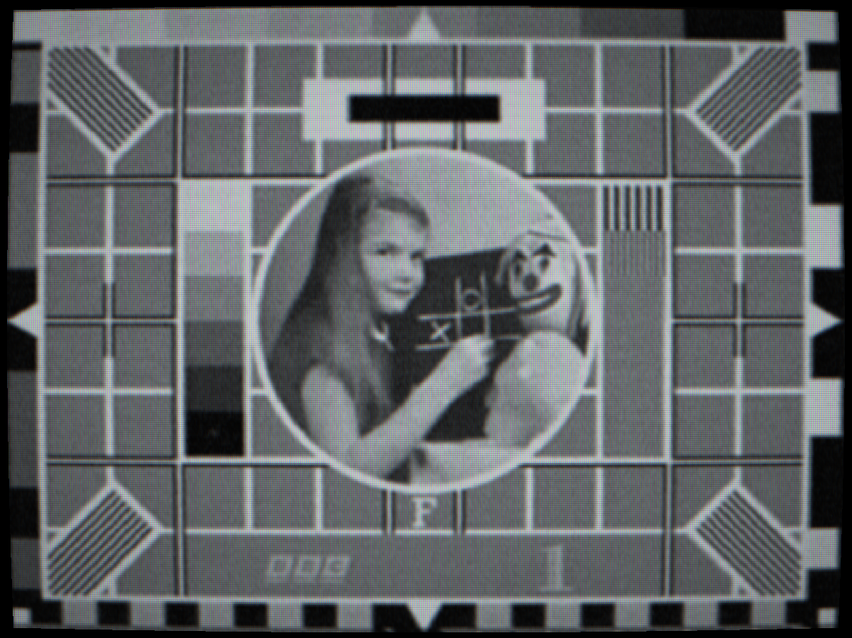
 SSTV MONO
CLEAN
SSTV MONO
CLEAN
Slow-scan raster vs. the clean source
Controls
Selects which Apollo television format drives the signal chain. Both are gated to the Apollo group and share no state with the broadcast standards.
SSTV Mono (Apollo 7–11 lunar-surface & cabin camera) — Slow-scan monochrome: 320 lines, 10 frames per second, progressive, 4:3, in a ~500 kHz channel. Horizontal sync was carried as bursts of a 409.6 kHz sine wave phase-locked to the camera clock rather than as a level. Far too narrow and too slow for a home receiver; it was always re-scanned on the ground (see Ground Processing). Encoded by a dedicated CPU slow-scan encoder, not the GPU broadcast path.
Field-Sequential Colour (Apollo 10+ command module & Lunar Rover) — A 525-line / 59.94-field signal whose colour comes not from a subcarrier but from a six-segment RGB filter wheel spinning at 9.99 rev/s in front of a single tube, so each successive field records one primary. The colour video band is only a little over 2 MHz — narrower than a full broadcast channel — so the recombined picture is softer than its line count suggests. A single still frame shows one monochrome primary; colour appears once the ground converter recombines successive fields (visible in motion).
Two intensified camera tubes were flown on Apollo, each paired with one format. They appear in the camera-tube list only while an Apollo format is selected.
SEC (Westinghouse Secondary Electron Conduction) — The lunar-surface monochrome tube. Its plano-concave fibre-optic faceplate carried characteristic blemishes, and the high-gain secondary-electron target produced a distinctive highlight response. Used for the Apollo 11 moonwalk and the lunar SSTV format.
SIT (RCA Silicon Intensified Target) — The colour-camera tube behind the field-sequential RGB wheel (Apollo 10+ command module and the Lunar Rover GCTA). High sensitivity for the low light levels of the cabin and the lunar surface; paired with field-sequential colour.
Enables the ground-station stage that stood between the spacecraft downlink and the broadcast networks. For the slow-scan format this is the optical scan converter: the 10 fps picture was displayed on a long-persistence monitor and re-photographed by a conventional 525-line / 30 fps NTSC camera, generating six NTSC fields per slow-scan frame to fill the rate gap. The monitor-and-camera optics measurably lowered contrast, brightness and resolution and added the small white spots familiar from the Apollo 11 footage.
For the field-sequential colour format this same stage performs the colour recombination: it recovers the colour-field phase from the in-signal flag (stamped on line 18) and accumulates successive R, G and B fields into a single full-colour picture — exactly as the ground station did. Colour therefore appears only with Ground Processing enabled and a colour tube selected.
Models the Apollo S-band signal path between the Earth and the Moon. The distance applies a one-way propagation delay (distance ÷ c) to a live feed — ~1.21–1.35 s at the real perigee-to-apogee range (mean 384,400 km) — plus a subtle 1/r² path-loss noise rise.
Near lunar range the picture also breaks into impulsive black-and-white FM-threshold "clicks." The downlink was frequency-modulated, and at the Moon's distance it ran below the receiver threshold on the 85-foot ground dishes (only Goldstone's 210-foot antenna stayed comfortably above it). Below threshold an FM demodulator sprays impulse noise rather than fading gently. There is deliberately no smooth dimming with distance: the real path-loss variation over the orbit was under 1 dB and the S-band AGC removed it, so the app adds none. The delay is meaningful only for a live source.
Signal-domain reproduction
Every Apollo artefact is derived from the simulated signal, not painted over a clean image: the slow-scan line count and ~500 kHz bandwidth, the field-sequential colour phase carried in the signal, the scan-converter optical degradation, and the FM-threshold clicks all emerge from the same signal chain the broadcast standards use. The formats are gated and isolated — selecting Apollo never affects the NTSC/PAL/SECAM path.
Sources
NASA TN D-7476 (Coan, 1973), the RCA Ground-Commanded Television Assembly manual, and the Apollo S-band telemetry record. See the Apollo section on the home page for the full historical narrative.