 GHOSTING
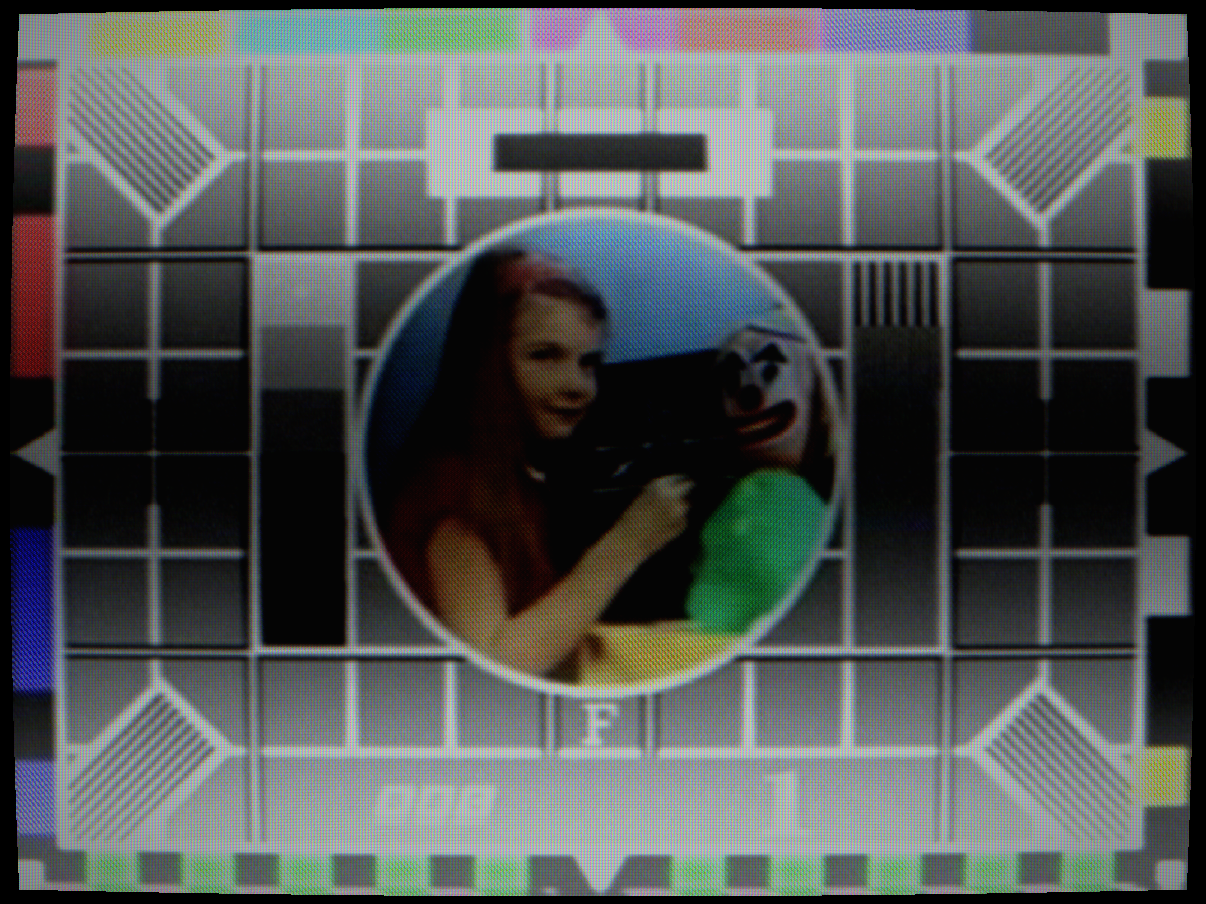
CLEAN
GHOSTING
CLEAN
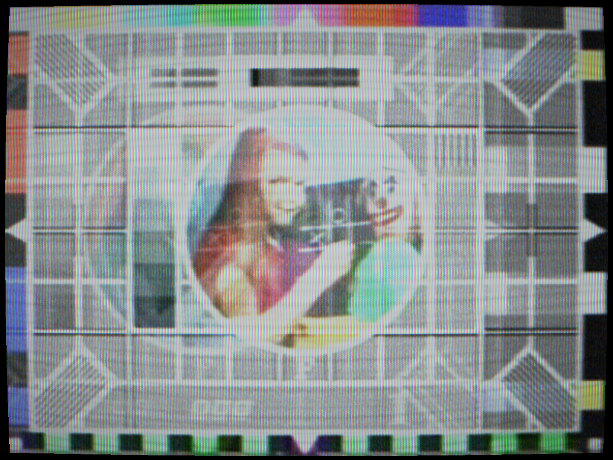
Multipath ghosting: reflected signal echoes
 HUM BARS
CLEAN
HUM BARS
CLEAN
50 Hz hum bars: mains interference on PAL
 CO-CHANNEL
CLEAN
CO-CHANNEL
CLEAN
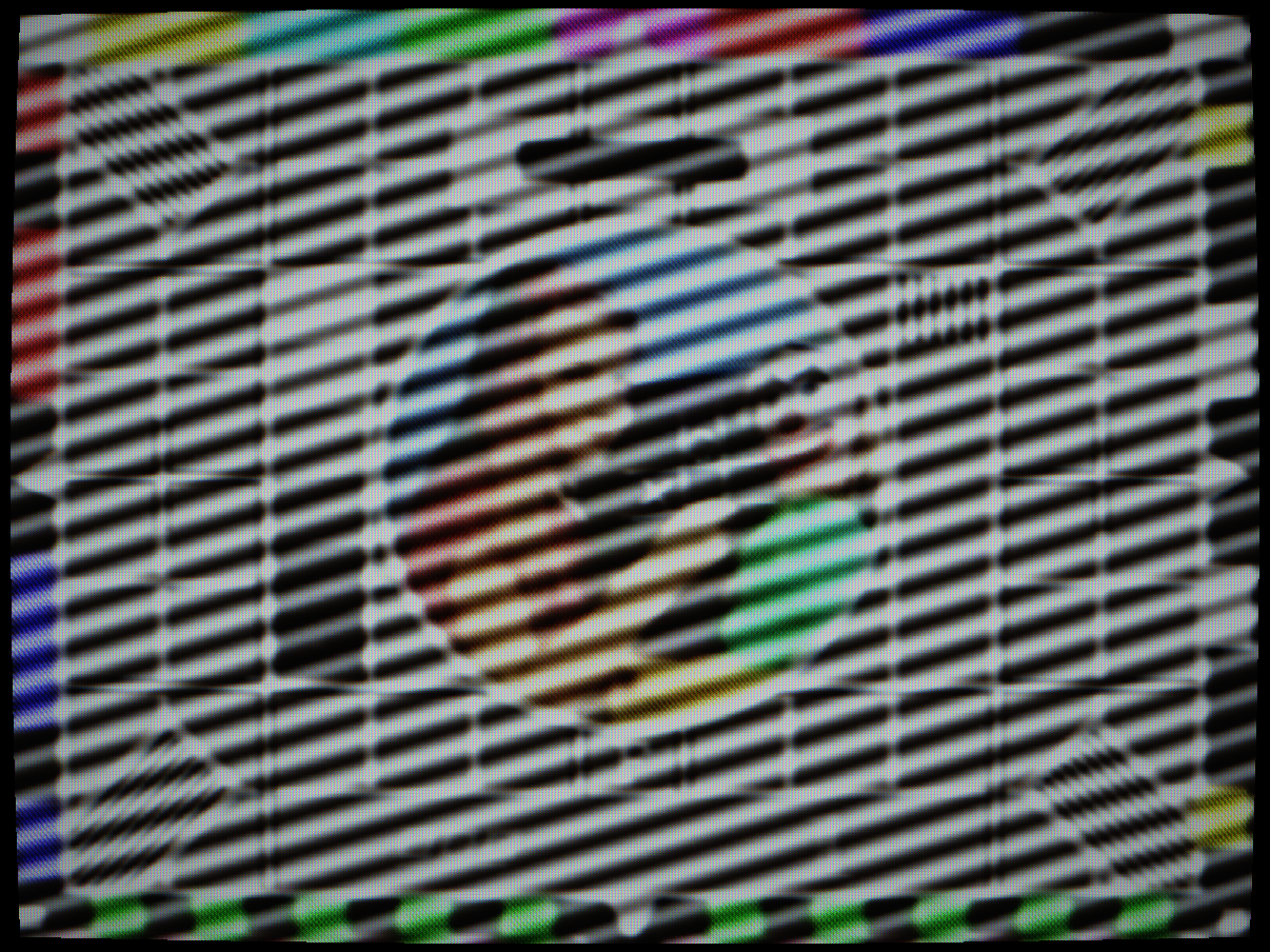
Co-channel interference: distant transmitter beat pattern
 IMPULSE
CLEAN
IMPULSE
CLEAN
Impulse noise: spark/ignition spikes across the picture
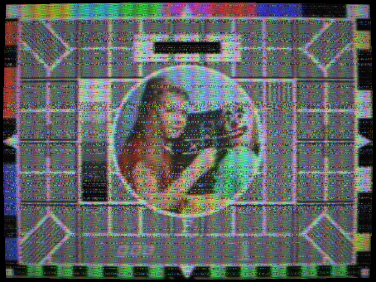
 SNOW
CLEAN
SNOW
CLEAN
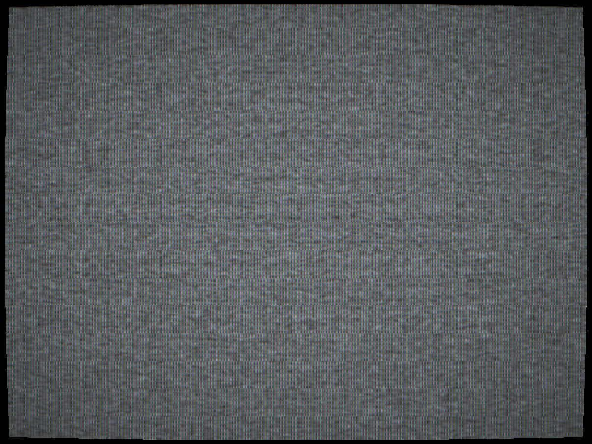
Television snow: off-air thermal noise through a P22 CRT
Controls
Multipath signal reflections. The transmitted signal arrives at the aerial by multiple paths: direct line-of-sight plus one or more reflected paths (off buildings, hills, aircraft). The reflected path is longer and therefore arrives later, producing a delayed copy of the image at a horizontal offset proportional to the delay. Three independent ghost sources are available, each with independent strength and delay.
Ghost delay is measured in composite sample periods. At 4×fsc NTSC sampling (14.32 MHz), each sample corresponds to 70 ns of propagation delay, equivalent to about 21 m of path length difference. A delay of 22 samples corresponds to a path length difference of ~462 m, the typical distance to a large building reflection.
Ghost polarity is always positive (the delayed copy adds to the direct signal). In real receivers, negative-polarity ghosts also occurred from phase-inverting reflections.
Interactions: Multiple ghosts compound. Ghost 2 and Ghost 3 add to Ghost 1’s output. Ringing Strength adds additional shorter-delay echoes from IF filter resonance, which look similar to weak close-in ghosts.
How to test: Set Ghost 1 Strength to 0.35, Delay to 22 samples. View a colour-bar source. A faint displaced copy of the bars appears to the right of the originals at a distance proportional to the delay setting.
Mains frequency interference. When the mains supply (50 Hz in Europe, 60 Hz in the Americas) couples into the video signal path through inadequate power supply filtering or a ground loop, it adds a sinusoidal modulation to the video level. This appears as slow horizontal brightness bands that travel upward through the frame at a rate determined by the beat frequency between the mains frequency and the field rate.
For PAL (25 fps, 50 Hz mains): the 50 Hz exactly equals 2× the field rate, so the two hum bands are stationary in the frame unless there is a slight frequency error. For NTSC (29.97 fps, 60 Hz mains): the hum bands drift slowly upward at the beat frequency between 60 Hz and 59.94 Hz (the field rate).
Interactions: Hum bars are completely independent of other artefacts but look more realistic when combined with mild signal noise. The mains frequency automatically follows the selected TV standard.
How to test: Set to 0.4 on a flat grey source. Two slow horizontal bands of alternating lighter and darker grey drift through the frame. On PAL they move very slowly (or appear nearly stationary); on NTSC they drift upward at the NTSC/mains beat rate.
Distant transmitter beating. When a distant television station transmits on the same channel frequency as the local transmitter, its carrier arrives at the receiver at a slightly different frequency (due to slight channel frequency tolerances). The two unresolvable carriers beat against each other, producing a slowly moving diagonal herringbone interference pattern, a fine diagonal grid that crawls across the image.
The crawl rate is determined by the frequency offset between the two carriers (typically a few hertz for real stations on nominally the same channel). The pattern is most visible on flat areas of the image because the herringbone amplitude-modulates the luma level.
Interactions: At high strengths, the co-channel pattern is visible even over detailed image content. Combining with mild Noise Level makes it harder for the eye to separate the co-channel from the noise floor, as experienced when the local transmitter had only slightly better signal than the interfering station.
How to test: Set to 0.5 and view a solid grey background. A slowly moving diagonal herringbone grid becomes visible. The crawl rate changes slightly over time as the beat frequency drifts.
Spark and ignition interference. Car ignition systems, fluorescent light ballasts, electric motors and switched-mode power supplies generate broadband RF pulses that couple into the aerial and appear as short high-amplitude spikes on the composite signal. After decode, these appear as bright white (or occasionally dark) flashes at random positions across the image, the characteristic “sparkles” associated with interference from passing cars or industrial equipment.
The arrival of each impulse is random (Poisson process). Duration per event is very short, a single pulse typically affects only 1–3 pixels horizontally. Amplitude is high, individual impulses clip to peak white.
Interactions: Unlike Noise Level (which adds Gaussian noise to every sample), Impulse Noise is sparse, most samples are unaffected but a small fraction are completely corrupted. This makes the two visually distinctive: Gaussian noise looks like uniform grain; impulse noise looks like random sparkles.
How to test: Set to 0.4 and view any source. Random white sparkles appear scattered across the image, no two frames are the same. Increase to 0.7 for heavy ignition interference levels as experienced near major roads.
Deflection yoke resonance. The horizontal deflection coil is an inductor that resonates at its self-resonant frequency. During the horizontal flyback period, the yoke is driven into resonance; this oscillation persists briefly into the visible scan period, creating a short damped oscillation visible as faint horizontal ripples at the left side of the image, just after the line start.
The frequency and amplitude of the ring depend on the yoke inductance and the damper diode characteristics. In well-designed sets the damper diode quenches the ring quickly; in poorly-designed or ageing sets with failing damper diodes, the ring persists longer and is more visible.
Interactions: Looks similar to multipath ghosting at very short delays (1–3 samples) but is physically distinct, ghosting affects the whole line, while yoke ringing only appears at the left edge and decays toward the right within the same line.
How to test: Set to 0.6 and view a white image. Look at the left 10–20% of the frame, faint horizontal bright/dark ripples are visible extending from the left edge, decaying toward the centre. They are constant across all lines (not spatially random like noise).
Beam horizontal speed modulation. Introduced by Toshiba and adopted widely in consumer CRTs during the 1990s–2000s, SVM modulates the horizontal scanning speed of the electron beam proportional to the luma gradient. Where the luma rises (dark-to-bright transition), the beam slows down, spending more time on the bright area. Where it falls (bright-to-dark), the beam speeds up. The net effect is that bright areas at transitions are expanded and dark areas are compressed, making edges appear sharper to the viewer without actually improving the signal bandwidth.
The artefact is a hallmark of late consumer CRTs: edges look artificially crisp but are surrounded by a characteristic ringing/halo artefact. High-quality broadcast monitors and professional sets typically disabled or attenuated SVM.
Interactions: SVM operates on the composite luma gradient. High Ringing Strength alongside SVM creates a compounding edge enhancement that looks dramatically over-sharpened. SVM has no effect on chroma, colour smearing at edges remains unchanged.
How to test: View a sharp black/white vertical boundary. Increase SVM Strength, the white area immediately adjacent to the boundary brightens and the black area immediately adjacent darkens. The transition still has the same underlying bandwidth but appears sharper. Look carefully for the associated ringing on the far side of each edge.