
 DOT CRAWL
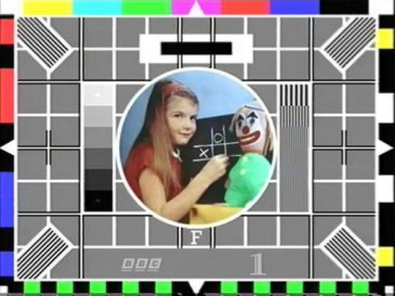
CLEAN
DOT CRAWL
CLEAN
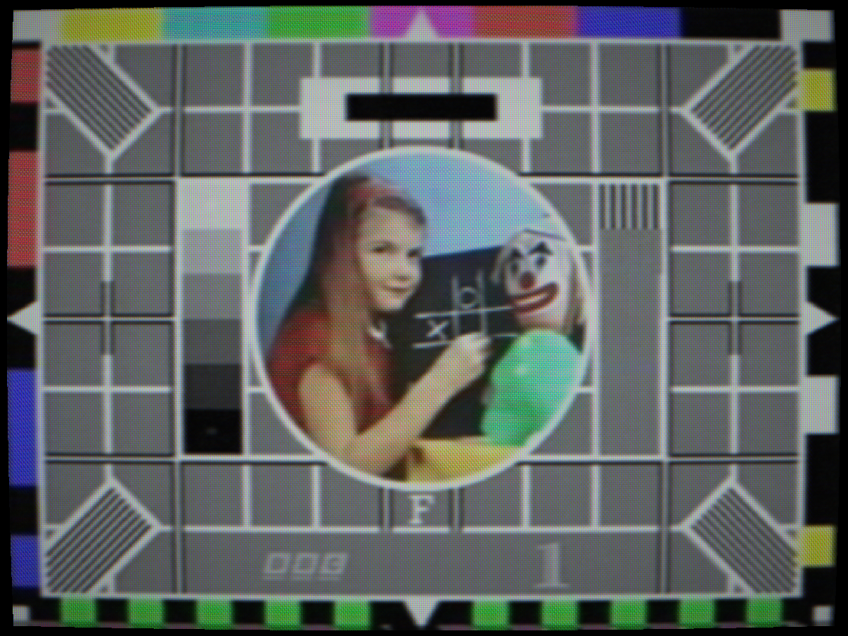
NTSC dot crawl: cross-colour at luma/chroma edges
 HANOVER BARS
CLEAN
HANOVER BARS
CLEAN
PAL Hanover bars: delay-line phase error
 B&W MODE
COLOUR
B&W MODE
COLOUR
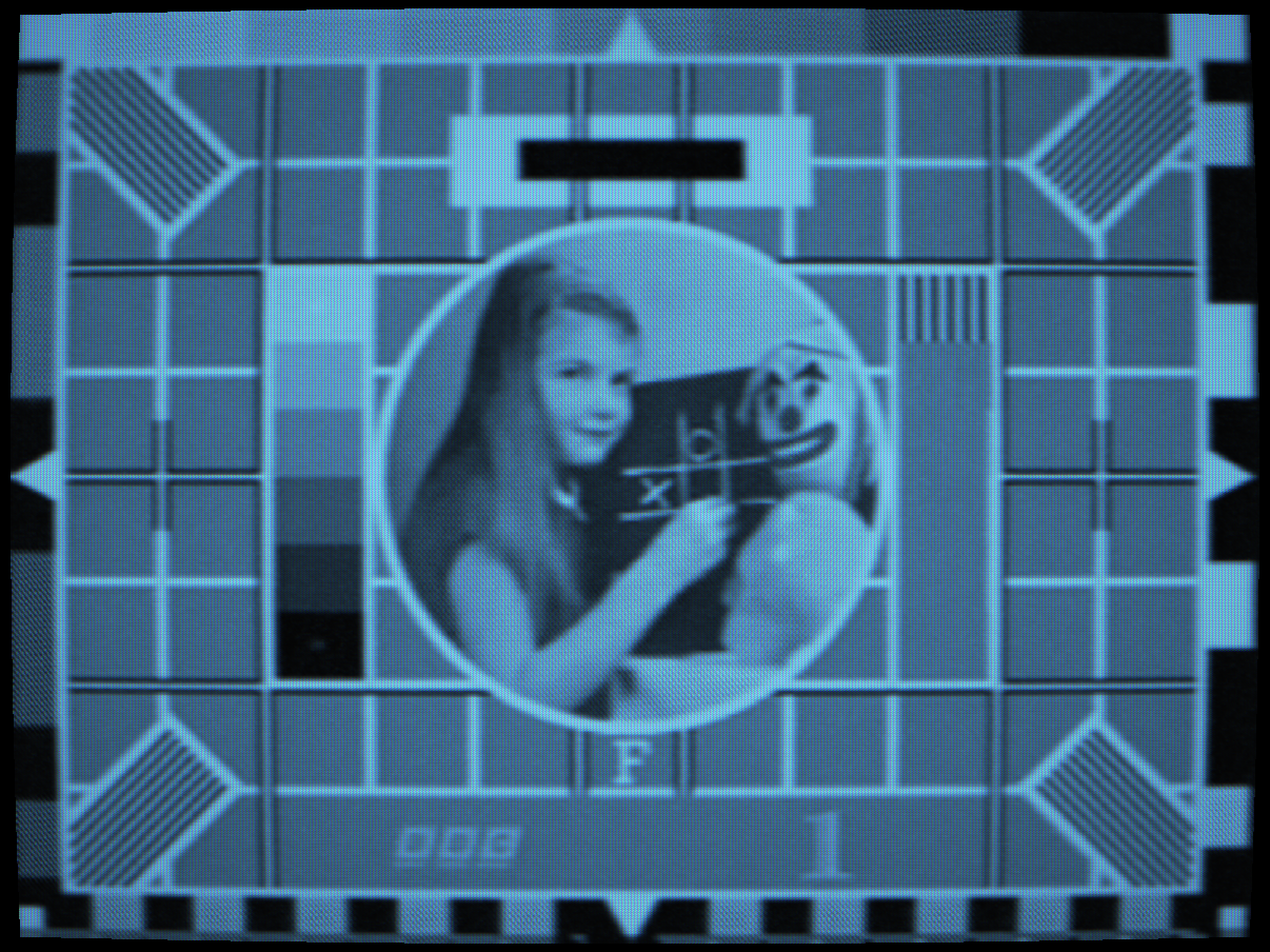
Black & white mode with P4 phosphor colour temperature

 NARROW IF
CLEAN
NARROW IF
CLEAN
Narrow IF bandwidth: ringing and dot crawl from a misaligned filter

 VECTORSCOPE
PICTURE
VECTORSCOPE
PICTURE
Vectorscope: colour-difference phase display
Controls
Selects the broadcast encoding standard used to convert the scene into a composite waveform. Each standard defines line count, field rate, colour subcarrier frequency, chroma encoding method and video bandwidth.
NTSC-M (525 lines, 29.97 fps, 3.579545 MHz QAM, 7.5 IRE pedestal), North American standard from 1954. Phase-sensitive: any path error rotates hue. The “tint” control on the receiver corrects for this.
PAL B/G/I/D/K (625 lines, 25 fps, 4.43362 MHz), Western European standard from 1967. The V-switch on alternating lines auto-corrects phase errors that plagued NTSC. Receivers need no manual tint control, hence “Phase Alternating Line”.
SECAM (625 lines, 25 fps, FM chroma), French standard. Db and Dr chroma are transmitted on alternate lines, the missing component retrieved from a one-line delay. FM-immune to path phase errors but completely incompatible with NTSC/PAL demodulators.
D-MAC / D2-MAC / MUSE / HD-MAC, Time-division multiplexed satellite and HDTV standards from the 1980s–90s. Luma, chroma, audio and data occupy separate time slots within each line. No colour subcarrier.
B&W standards, 405-line (System A, UK, 1936), 525-line (System M), 625-line, 819-line (System C, France). No colour subcarrier; luma-only AM modulation.
Interactions: Switching standard changes all downstream artefacts. Dot crawl is NTSC-specific. Hanover bars are PAL-specific. SECAM shows fire artefacts at colour transitions. Signal Domain Mode’s accuracy improvement is most visible on NTSC.
How to test: Use colour bars as the source. Switch between NTSC and PAL; the subcarrier-related crawl patterns change completely. Switch to SECAM; observe the FM chroma ringing at colour boundaries.
Strips the chroma component before encode, sending only the luminance (Y) channel through the composite signal chain. The output colour is then entirely determined by the CRT phosphor type selected, this is physically accurate: a monochrome CRT has a single phosphor with a specific emission colour, not the three-phosphor RGB triad of a colour set.
P4 phosphor gives a warm near-white output characteristic of B&W television sets. P31 gives the classic green oscilloscope display. P3 gives amber. P11 gives deep blue. Each is modelled from measured spectral data.
Interactions: The combination of Black & White Mode + CRT Phosphor Type is the primary tool for simulating historical monochrome displays. Use with the 405-line or 819-line standard and Image Orthicon camera type for a complete pre-colour broadcast chain.
How to test: Switch B&W Mode on with the default P22 phosphor, the image should be monochrome with the P22 blue-white colour temperature. Switch to P31 (the image should become the characteristic oscilloscope green. Switch to P4) warm white, matching a 1950s domestic TV set.
NTSC cross-colour interference. In NTSC, the colour subcarrier (3.58 MHz) is interleaved with the luminance spectrum so they share the same cable without a separate channel. Where luma energy falls near 3.58 MHz, it is misinterpreted by the chroma decoder as colour information, and vice versa. At colour boundaries, the two signals beat against each other, producing the characteristic moving diagonal crawl of coloured dots.
The artefact moves upward at the NTSC frame rate because the subcarrier phase shifts by 180° every field (NTSC’s half-line frequency offset). PAL does not exhibit dot crawl because its V-switch inverts the phase, cancelling the cross-talk.
Interactions: Dot crawl is only active on NTSC standards. Signal Domain Mode makes the dot crawl more accurate by computing subcarrier phase at full sample rate. Higher Saturation increases the chroma energy and therefore worsens crawl at luma boundaries.
How to test: Switch to NTSC, select colour bars. Set Dot Crawl Strength to 1.0. Look at the sharp luma/chroma boundary between the white and grey regions, a diagonal crawling pattern of coloured dots is visible and moves slowly upward frame by frame.
PAL delay-line phase error. In PAL, the V-axis of the chroma signal is phase-inverted on alternating lines. A one-line delay stores the previous line’s V component; the decoder averages the current and delayed V to cancel path phase errors. If the delay line introduces a slight phase offset, alternate lines receive slightly different V phases and decode to slightly different hues, visible as alternating horizontal bands of mismatched colour.
The artefact is named after the Hanover (Fernseh) PAL decoder design that first exhibited it. High-quality PAL decoders used precision glass delay lines to minimise the error; cheap sets used cheaper delay lines and exhibited stronger Hanover bars.
Interactions: The PAL Delay Line Offset control (in the signal settings) exaggerates the phase error to make the bars more obvious. Hanover Bars Strength scales the amplitude of the per-line hue error introduced.
How to test: Switch to PAL, view colour bars. Set Hanover Bars Strength to 1.0. Look at a saturated colour field; alternating lines will have a slightly different hue, creating a fine horizontal banding pattern.
IF filter resonance post-edge overshoot. The IF (intermediate frequency) filter in the tuner and signal chain has a passband edge near 5 MHz. A misaligned or low-Q filter resonates briefly after a sharp transition in the video signal, creating a damped oscillation, visible as alternating bright/dark ghost copies of sharp vertical edges, extending to the right.
The number of visible rings and their decay rate depend on the filter Q factor. A high-Q filter produces many sharp rings; a low-Q filter produces fewer, broader rings. This is also how the “edge enhancement” controls on consumer CRTs worked, controlled ringing made edges look sharper.
Interactions: Ringing Strength in this section affects the composite signal path. A separate Camera Ringing Strength control applies the same model to the camera tube’s optical ringing at the photoconductive layer edges. They compound additively.
How to test: View a sharp black/white vertical edge. Increase Ringing Strength, ghost copies of the edge appear to the right of the original, alternating in polarity (first bright, then dark, then bright again).
When enabled, the composite signal is synthesised at full sample rate (4×fsc for NTSC, 4×fsc for PAL) rather than at output display resolution. This means the subcarrier phase relationships are computed per composite sample, not approximated at screen pixel resolution.
The result is more accurate subcarrier phase coherence across the frame, more realistic dot crawl texture, correct chroma bleeding at boundaries, and more authentic Y/C cross-talk. The downside is higher GPU workload.
Interactions: The improvement is most noticeable on NTSC where the half-line frequency offset creates a specific 3D comb structure. On PAL the improvement is subtler due to the V-switch cancellation. SECAM is always computed in the signal domain because FM chroma cannot be approximated at display resolution. Signal Domain Mode is required for Pay TV scrambling, selecting any Pay TV mode (Sync Suppress, Video Inversion, Cut-and-Rotate or Line Shuffle) enables it automatically.
How to test: Switch between on and off while viewing NTSC colour bars with Dot Crawl Strength at 1.0. The dot crawl texture changes from a smooth approximation to the authentic finer-grained diagonal pattern seen on real NTSC monitors.