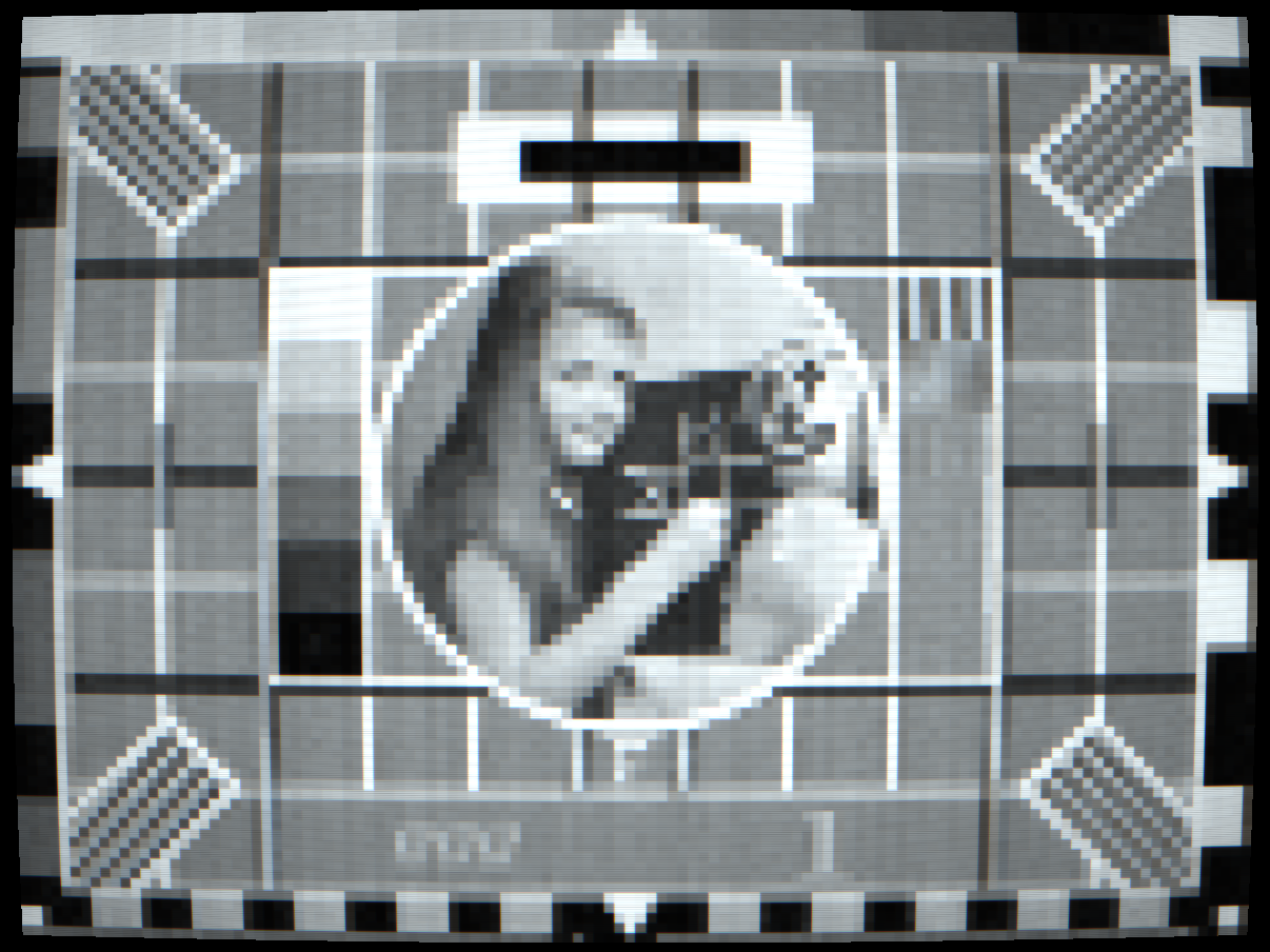
VHS tracking loss: head/tape misalignment noise bars
 4TH GEN
ORIGINAL
4TH GEN
ORIGINAL
VHS generation loss: fourth copy degradation
 BETACAM SP
BYPASS
BETACAM SP
BYPASS
Betacam SP: broadcast component recording, 340 TVL
 PXL-2000
BYPASS
PXL-2000
BYPASS
PXL-2000: 120×90 px, cassette FM, no composite signal
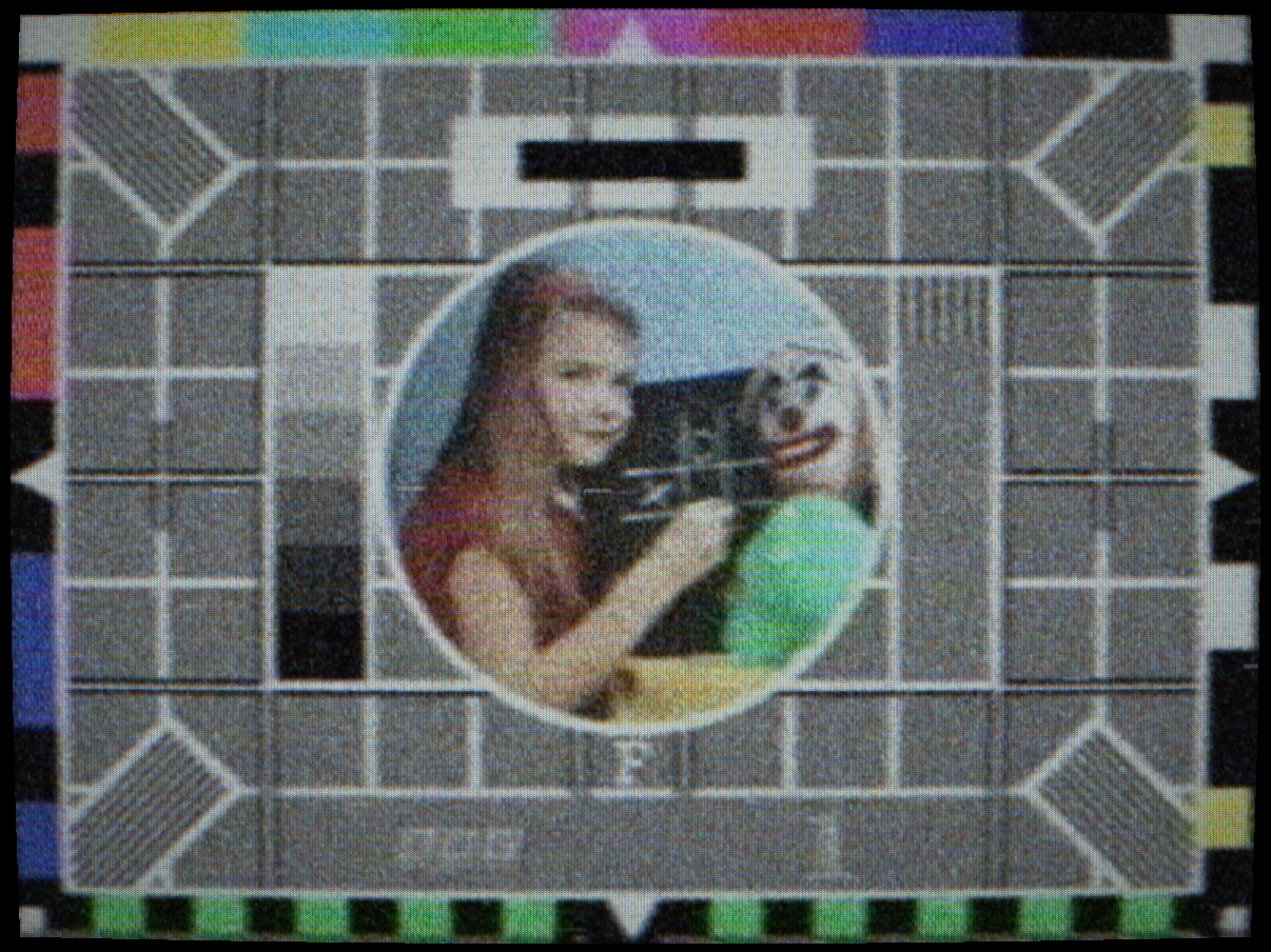
Macrovision Type 1 (AGC): VBI pulses make a copy recorder's gain pump every ~7.7 s

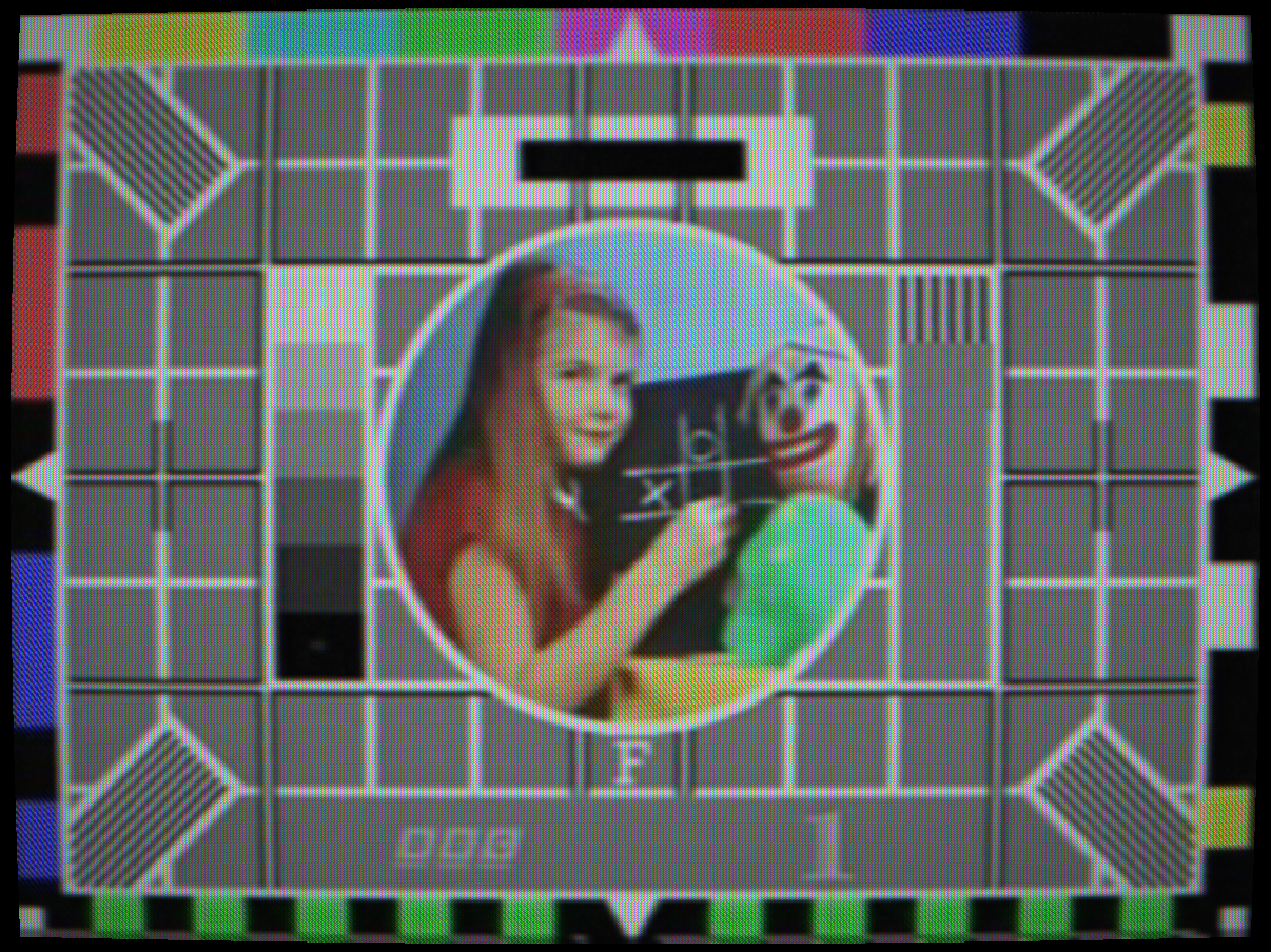
 COLORSTRIPE
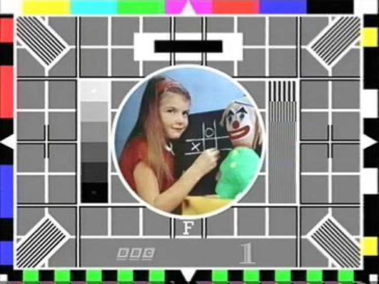
CLEAN
COLORSTRIPE
CLEAN
Macrovision Type 2 (Colorstripe): horizontal bands of wrong colour on the copy
Copyguard: truncated V-sync serration; a recorder cannot lock, so the copy rolls
Controls
Selects the tape recording format. Each format is characterised by its luminance recording bandwidth (TVL), the colour-under scheme used for chroma, oxide formulation and the resulting dropout statistics and mechanical transport precision.
VHS SP / LP / EP, 240 / 200 / 160 TVL. Colour-under at 629 kHz (NTSC) with 4H colour-under averaging. EP has the highest dropout rate and worst chroma noise due to the shorter recorded wavelength at slower tape speed.
S-VHS, 400 TVL. Y and C are recorded separately on separate tracks. Dramatically better luma bandwidth; compatible VHS colourunder chroma path. Requires S-VHS compatible tape (ME formulation).
Betamax, 250 TVL. Slightly better oxide than VHS SP but same colour-under principle. Sony’s half-inch consumer format, lost the format war despite often superior picture quality.
U-matic, 240 TVL. 3/4-inch professional/prosumer format. First colour-under cassette format (1971). Used extensively in broadcast ENG until the late 1980s.
Betacam SP, 340 TVL. Component Y/R-Y/B-Y recording using FM modulation, no colour-under. Y and both colour-difference channels recorded on separate heads. Near-broadcast quality; near-zero chroma phase noise because there is no colour-under heterodyne to drift.
8mm / Hi8, 240 / 400 TVL respectively. Metal-evaporated tape in a compact cassette. 8mm uses audio FM depth-multiplexed into the video tracks; Hi8 uses the same scheme as S-VHS Y/C separation but in the smaller cassette.
Interactions: Each format changes the defaults for Tracking, Dropout, Luma Noise and Chroma Phase Noise. Betacam SP disables Chroma Phase Noise because it uses component recording. Generations loss compounds more severely with low-bandwidth formats.
How to test: Switch from VHS-EP to Betacam SP on a colour-bar source. The difference in horizontal resolution, colour fidelity and noise floor is immediately visible, the same difference that made Betacam SP the dominant broadcast acquisition format from 1986 to the early 2000s.
Head/tape alignment error. VHS heads must follow the helical tracks written by the recording machine. If the playback machine’s head geometry differs from the recording machine (different machines, worn mechanics, or a mis-set tracking control), the heads straddle two adjacent tracks and read a noisy mix of both, visible as a horizontal noise bar. At higher values, complete dropout bands appear as pure noise rectangles.
The noise bar drifts upward because the servo lock phase slips slightly each field, causing the bar to rise at the field rate until it wraps around the frame edge. This gives the characteristic “rolling” noise band seen on poorly-tracked VHS tapes.
Interactions: Combines with Skew, skew distorts the edges of the noise bar. At high Tracking + high Skew values the bar appears tilted and its edges zigzag. VHS-EP has the smallest head guard band and therefore the lowest tolerance for tracking error before dropout appears.
How to test: Set Tracking to 0.5 on VHS-SP. A horizontal noise band appears roughly one-quarter up the frame and drifts slowly upward. Adjust toward 0 to simulate the effect of tuning the tracking control on the VCR front panel.
Random oxide loss events. As the oxide coating wears off the tape, areas of missing signal appear as white or dark horizontal streaks of random length and position. The simulation models dropout events with a Poisson process, random arrival times and exponentially distributed durations, calibrated to the dropout rates measured for each tape formulation. VHS-EP at the extreme end of wear has roughly 4× the dropout rate of VHS-SP on fresh tape.
Real VCRs used dropout concealment circuits that substituted the previous line for the dropped line. The simulation does not apply concealment by default, giving the raw uncorrected dropout appearance.
Interactions: Combines with Tracking, high Tracking already loses large blocks of signal, so Dropout mainly adds the fine random sparkle on top. VHS-EP format inherently has higher dropout than SP from its shorter recorded wavelength.
How to test: Set Dropout to 0.2 on VHS-SP. Random white and dark horizontal streaks appear scattered across the image on random lines each frame. Increase to 0.5 for heavily worn tape levels.
Tape-path noise added to the luminance FM carrier. The luminance signal is recorded as an FM waveform on VHS; noise in the tape oxide layer amplitude-modulates this carrier, which after FM demodulation appears as additive noise on the Y channel. VHS HiFi audio tracks use depth-multiplexing into the same tape area, which can cross-couple as a regular beat pattern at very high luma noise levels.
Interactions: Adds to Signal Noise Level in the final composite decode. Camera Noise adds to luma before encode; Luma Noise adds to luma after the VCR decode stage. The two both appear as grain but have slightly different spectral character because one has been through the composite encode/decode chain and one has not.
How to test: Set to 0.3 and view a flat grey field. Additive grain is visible. Compare the texture with Camera Noise at the same level, they look similar but the Luma Noise grain has slightly coarser texture from the FM bandwidth limiting.
Colour-under subcarrier phase jitter. In all colour-under VCR formats (VHS, Betamax, 8mm, U-matic), the colour subcarrier is heterodyned down to a low frequency (629 kHz for VHS-NTSC) for recording. On playback, the recovered subcarrier phase jitters randomly due to capstan speed instability and tape tension variations. This phase jitter demodulates directly as hue and saturation instability: saturated colours appear to breathe and shift hue slightly from field to field.
The effect is worst in VHS-EP (lowest recorded wavelength, highest phase noise from shorter signal) and non-existent in Betacam SP (component recording bypasses colour-under entirely).
Interactions: Flutter affects capstan speed directly and therefore worsens Chroma Phase Noise. The two effects are physically coupled in real VCRs. Very high Chroma Phase Noise combined with high Saturation makes colours appear to swirl or pulse.
How to test: Set to 0.4 on VHS-SP with a fully saturated colour (pure red or blue). Watch the colour over several seconds, it shifts slightly in hue and pulses in saturation each field, giving the characteristic “breathing colour” look of worn VHS tapes.
Capstan speed variation causing horizontal displacement at the head switch point. Each helical-scan VHS track begins and ends at the head switch, at the bottom of the frame. If tape tension varies during the scan, the start-of-track position is displaced horizontally relative to the previous scan, creating a progressive horizontal lean that resets each frame at the head switch point.
At mild levels this produces the characteristic bottom-lean seen on worn tapes. At severe levels the bottom of the frame becomes a chaotic horizontal smear.
Interactions: Combines with Flutter (flutter is faster variation; skew is slower, per-scan). Head Switch Strength determines how visible the reset glitch is at the frame bottom where the skew resets each field.
How to test: Set to 0.3 on VHS-SP and view vertical lines. The bottom of the image tilts left or right. The tilt direction reverses each few frames as the capstan phase varies.
Tape copy generation loss. Each re-recording pass applies a complete additional tape noise floor, further limits the luminance bandwidth, and reduces chroma saturation. The losses compound: a 4th-generation copy has been through the tape noise floor four times, each pass adding noise and limiting bandwidth independently. This is physically accurate, every VHS dubbing pass degrades picture quality in exactly this way.
At generation 4–5, the image has noticeable horizontal blurring, elevated grain, and washed-out colours. At generation 8–10, the picture quality approaches the threshold of legibility, as seen on heavily-dubbed VHS copies of bootleg concert videos or grey-market cassette copies from the 1980s.
Interactions: Generations multiplies the effect of Luma Noise and Chroma Phase Noise, both get worse with each generation. The luma bandwidth limiting also compounds, so each generation reduces the effective TVL rating of the format further.
How to test: Set Generations to 1, view a fine pattern. Increase to 4 and compare, horizontal resolution clearly decreases, the grain floor rises, and saturated colours look less vibrant.
Copy Protection
Three commercially deployed analogue copy protection systems are simulated from first principles, operating entirely on the composite waveform. All require Signal Domain mode. Each system exploits a specific weakness in the consumer VCR recording circuit, the resulting artefacts appear only on illegal copies, not on the original signal.
Selects the copy protection system to simulate on the composite waveform. The signal entering any TV or monitor is unchanged (the protection is invisible on direct display) but the same signal recorded by a VCR exhibits severe degradation on playback.
Macrovision AGC (1984), Invented by John O. Ryan, Patent US 4,631,603. Inserts two distinct pulse types into Vertical Blanking Interval lines, commonly lines 10–20 per field. The first is a positive bright-white pulse at 100–125 IRE (approximately 150% of peak white); the second is a negative pseudo-sync pulse at sync-tip level (≥1 µs), placed immediately before the positive pulse (≥3 µs). On a television these are invisible (VBI lines are blanked) but the recording VCR’s AGC circuit reads the excessive level and attenuates gain to compensate. Active video records dark. Over 7–8 seconds the AGC slowly recovers, then fires again at approximately 0.13 Hz, an unmistakeable slow, rhythmic fade. At the bottom of the cycle, burst amplitude falls below ACC lock threshold and colour dropout occurs.
The negative pseudo-sync pulses cannot be distinguished from genuine H-sync by the recording VCR’s sync separator. Each false H-sync leaves the H-PLL at a wrong phase; all affected lines near the top of frame share the same base horizontal displacement, decaying exponentially over ~40 lines as the PLL re-locks. This is the “flagging” artefact: a block at the top folds sideways each frame, reversing direction frame to frame. The same pulses also reach the V-sync separator and can cause continuous rolling at high amplitude. Susceptibility varies by deck; many JVC VHS decks from c.1985 onward incorporated countermeasures. Later implementations also embed a CGMS-A “copy never” flag in VBI line 20.
Macrovision + ACP Level 2 (1994), Patent US 5,130,802. All AGC and sync disruption effects, plus Analogue Copy Protection colorstripe: every 17 scan lines a 2-line group has its colour burst phase inverted by 180° (NTSC) or alternating ±90° (PAL). The VHS colour-under AFC circuit locks to the wrong burst phase during each group and takes ~4 scan lines to re-acquire the correct phase at each group boundary, producing a grey colour-dropout zone. The in-group lines display complementary hues at full saturation. At maximum ACP Level, virtually every scan line carries a colour artefact.
Macrovision + ACP Level 3 (1994), As Level 2, but with 4-line inversion groups on a 21-line period, producing wider coloured bands.
Copyguard (1975), Developed by Trans-American Video Inc. (TAV). The V-sync broad-pulse serrations are truncated from 4.7 µs to approximately 1.5 µs. Standard TV sets tolerate this and lock normally. VCR recording circuits use a narrower timing gate tuned to the standard 4.7 µs serration; the truncated pulses fall below threshold and the copy’s V-oscillator free-runs, producing continuous vertical rolling on playback at approximately one roll every 10–20 seconds.
Interactions: All Macrovision modes require Signal Domain mode (enabled automatically on selection). AGC, sync disruption, and colorstripe effects each have independent sliders. Combining all three with a VHS format and high Generation Loss produces a copy that is genuinely unwatchable, historically accurate.
Controls the amplitude of the VBI bright-white pulses. At 1.0 the pulses reach 120–125 IRE (historically accurate). The recording VCR’s AGC responds by attenuating the composite signal to approximately 45% of nominal, making the picture very dark at the bottom of the cycle and much brighter than normal at the top. The asymmetric 0.13 Hz waveform (fast darkening over 30% of the period, slow recovery over 70%) is characteristic of the circuit response of consumer VCR AGC stages.
At high pulse amplitude, the suppressed composite level also causes colour dropout: burst amplitude falls below the chroma decoder’s ACC lock threshold and the colours desaturate toward grey. The dropout and recovery track the AGC cycle.
For Copyguard this slider controls the severity of the V-sync serration truncation rather than AGC pulses.
How to test: Set to Macrovision AGC with AGC Pulse at 1.0 and watch for 10–15 seconds. The picture cycles slowly between very dark (possibly grey, with colour dropout) and slightly over-bright, repeating every ~7.7 seconds.
Controls the amplitude of the false sync-level pulses injected alongside each AGC pulse in the VBI. These pulses interfere with two separate circuits in the recording VCR.
H-sync (flagging): The pulses are at H-sync tip level and can be mistaken for horizontal sync by the H-PLL. Each false H-sync leaves the PLL at a wrong phase when active video begins. All scan lines near the top of frame are horizontally displaced by the same base offset (the flag position for that frame), with exponential decay over ~40 lines as the PLL re-locks. The displacement changes direction every few frames as the phase error varies, producing the “flagging” artefact: the top third of the picture folds sideways as if a flag is waving. At maximum, lines near the top can shift by up to 40% of the picture width.
V-sync (rolling): The false pulses also reach the V-sync separator. At high Sync Disrupt, the separator accumulates phase errors faster than the V-PLL can correct, causing the picture to roll continuously. At full strength the roll rate is approximately 0.75 fields per second. Additional random impulse disruptions produce sudden vertical jumps on top of the roll.
How to test: Set Sync Disrupt to 1.0 with any Macrovision mode. The top ~40 scan lines will oscillate left and right each frame (“flagging”) and the picture will begin to slowly roll vertically within a few seconds. Lower values reduce both effects proportionally, below 0.3 the flagging is subtle and rolling is rare.
Controls the depth of the Analogue Copy Protection burst phase inversion. At 1.0 the burst is fully inverted (180° for NTSC, alternating ±90° for PAL) within each group. The VHS colour-under AFC circuit locks to the inverted phase during the group and must hunt back to the correct phase at the group boundary, a settling process spanning ~4 scan lines where chroma amplitude collapses near-zero, producing a grey colour-dropout stripe.
The decoded colours within each inverted group are the complementary hues of the original at full saturation, a face becomes cyan, a blue sky becomes orange, greens go magenta. The combination of complementary-colour bands and grey dropout zones across virtually every scan line makes protected content unrecognisable on a copied tape.
At lower ACP Level values the phase inversion is partial and the transition zones are narrower, producing a milder effect: slight colour banding with occasional grey stripes.
How to test: Select Macrovision + ACP Level 2, set ACP Level to 1.0 with colourful content. Wide horizontal bands of saturated wrong colours alternating with grey stripes will cover the entire frame, no area of the picture remains correctly coloured.