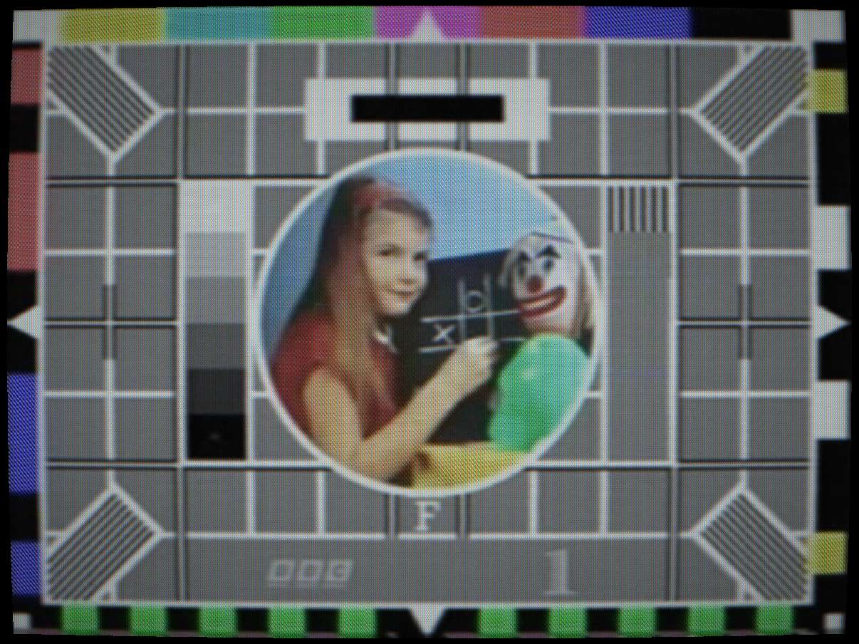
 SATURATED
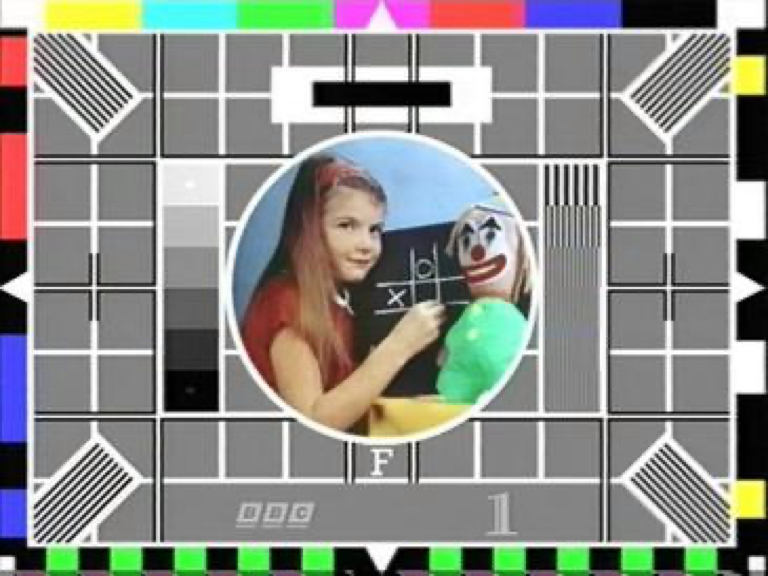
NORMAL
SATURATED
NORMAL
Saturation at 1.65×: colours bleed into adjacent areas
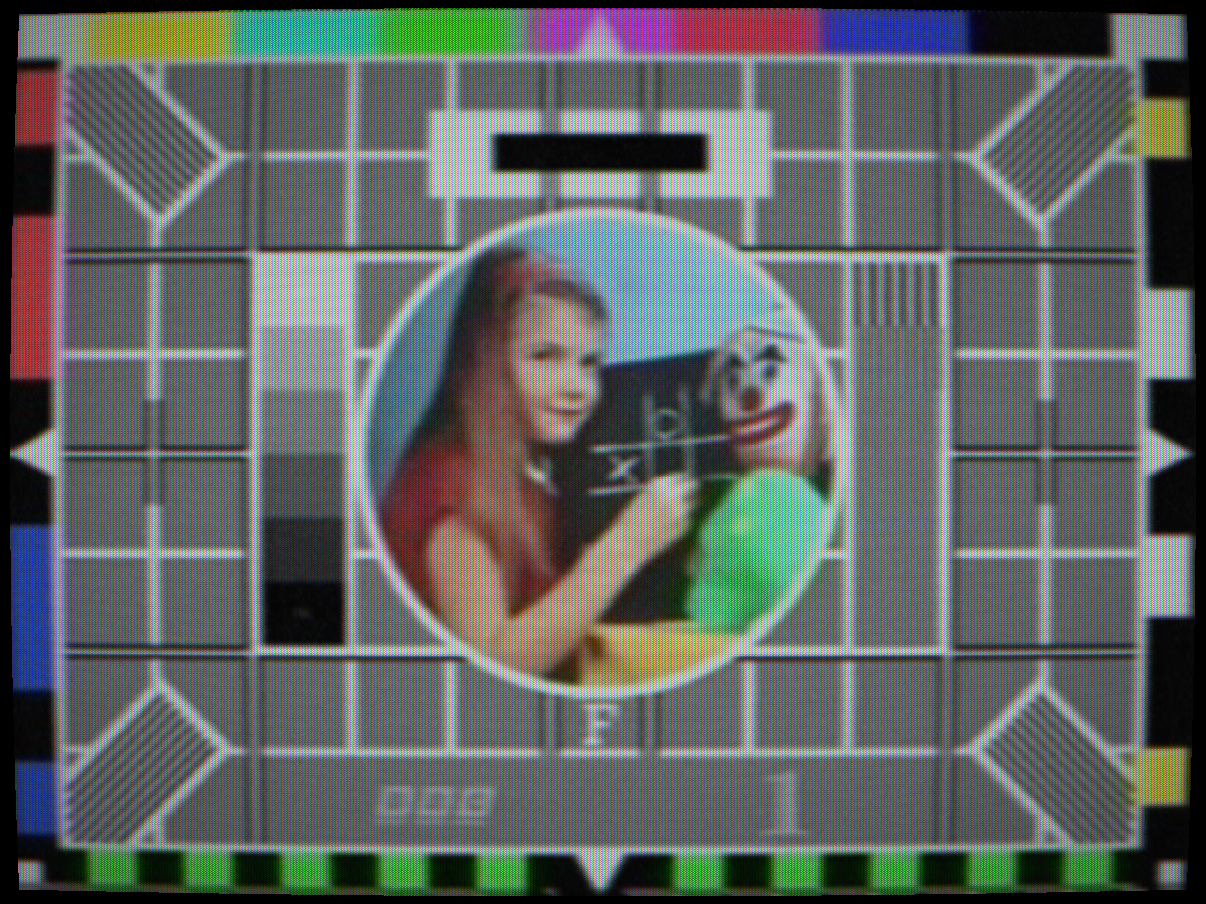
 HUE OFFSET
CORRECT
HUE OFFSET
CORRECT
NTSC hue offset +25°: uncorrected path phase error
Vertical hold loss: the picture rolls continuously as the field oscillator free-runs
Controls
Chroma decoder gain. Scales the amplitude of the decoded chroma (Cb and Cr) channels after the composite demodulator. This directly models the “Colour” or “Saturation” knob on the front panel of a television set, which adjusted the gain of the chroma amplifier stage in the decoder.
At 0.0, the chroma amplifier gain is zero, the output is monochrome despite the colour signal being present. This is subtly different from B&W Mode (which strips chroma before encode) because here the composite signal still contains chroma and the decode paths still process it, but the gain stage produces no output. At 2.0, oversaturation causes chroma to clip and bleed laterally into adjacent pixels.
Real sets often had slightly higher factory default saturation than the correct 1.0 value, because consumers responded more positively to vivid-looking colours in shop demonstrations. This is why early colour TV programming was often produced with somewhat desaturated colour grading, it was designed to look correct on a slightly over-saturated set.
Interactions: High saturation compounds with Dot Crawl (more chroma energy = more cross-colour artefact). High saturation with Chroma Phase Noise creates the “breathing colour” effect on worn tapes more vividly.
How to test: View colour bars. Set to 0 (monochrome output. Set to 1.0) correct. Set to 1.8, colours oversaturate; the red and blue bars start to bloom beyond their correct width.
Chroma phase offset. Rotates all decoded colours around the IQ or UV colour circle by the specified angle. In NTSC this is the famous “Tint” control that corrects for path phase errors in the transmission chain. Because NTSC uses quadrature amplitude modulation for chroma, any phase error in the path directly rotates the decoded colour. A 15° phase error shifts flesh tones from orange toward green or toward magenta. The tint control allowed the viewer to compensate for this.
PAL automatically corrects phase errors by averaging the V component over two lines (the V-switch), so the Hue control has minimal effect on PAL, the PAL decoder cancels any constant phase error. On SECAM, frequency modulation makes it phase-immune, so Hue has no effect.
The NTSC acronym “Never The Same Colour” refers to this susceptibility to path phase errors. American viewers routinely adjusted the tint control to correct for these errors as programme material was relayed across the country.
Interactions: Hue is NTSC-specific in its effect. On PAL it still rotates colours but the PAL V-switch partially compensates, leaving only a half-correction visible. On SECAM it has no visible effect.
How to test: Select NTSC, view colour bars. Set Hue to +20°, the cyan bar shifts toward green and the yellow bar toward green-yellow. The flesh-tone reference patches in EBU test cards visibly shift off their correct orange. Adjust back to 0° for correction.
DC level offset on the decoded luma channel, equivalent to the “Brightness” or “Black Level” control on the television set front panel. This control adjusts the bias point of the video amplifier, which sets the voltage at which the electron beam is cut off (the black level). Too low: shadow detail is crushed into pure black. Too high: the black level is raised, reducing contrast and making black appear grey.
In broadcast practice, the 7.5 IRE pedestal of NTSC-M is the standard black level, the video signal does not go below this level. The Brightness control shifts the effective mapping of “signal zero” to the display. NTSC-J (Japanese NTSC) uses a 0 IRE pedestal, giving slightly deeper blacks.
Interactions: Brightness and Contrast interact in the classic way: raising brightness while lowering contrast gives a “faded” look (raised blacks, compressed whites). Lowering brightness below −0.2 crushes all shadow detail. High Brightness with high Noise Level makes noise much more visible because the noise now rides on a grey floor rather than being clipped into black.
How to test: View the PLUGE bars in a test card (the three near-black bars below the reference white). Correct brightness has the lowest PLUGE bar just invisible and the highest just visible. Lower Brightness to crush all three into black; raise it to make all three clearly visible as grey.
Luma gain, equivalent to the “Contrast” or “Picture” control on the television set. Scales the luminance signal around the mid-grey point. Increasing contrast stretches the luma range: shadows fall faster to black and highlights clip to white earlier. At extreme values, the picture looks posterised because midtones are compressed into either shadow or highlight regions.
Real television sets used a potentiometer on the video amplifier stage for this control. The potentiometer’s centre point (50%) corresponded to correct gain; reducing it attenuated the video signal and increasing it amplified it. Very high gain settings overloaded the video amplifier and caused clipping, bloom and ringing at bright transitions.
Interactions: High Contrast with high Bloom Strength creates a look similar to an over-driven CRT that blooms at every highlight. The combination of Brightness and Contrast should be treated as a 2D adjustment: moving one typically requires compensating with the other to maintain the desired grey scale.
Vertical sync separator error. In analogue receivers, the vertical sync separator circuit detected the vertical sync pulse in the composite signal and locked the field scan rate to it. A variable RC time-constant controlled by the V-Hold control set the free-running frequency of the vertical oscillator. When this was adjusted away from the incoming field rate, the oscillator would lose lock and the picture would roll continuously at the beat frequency between the oscillator and the sync rate.
The rolling rate was determined by how far the V-Hold was misadjusted: just slightly off would cause very slow rolling (one roll every several seconds); far off would cause fast rolling. Viewers would tune the V-Hold control to lock the picture and then slightly back off to minimise hold-in noise.
Interactions: V-Hold rolling is combined with the head switch noise at the bottom of the frame, which becomes visible as the picture rolls through the frame edge. High Signal Noise makes the sync separator less reliable and can cause intermittent loss of lock even at V-Hold = 0.
How to test: Set V-Hold to 0.3. The picture begins to roll upward. Reduce toward 0 to simulate fine-tuning the hold control back to locked. The rolling rate decreases as you approach 0 and the picture locks at exactly 0.