
 PLUMBICON
CLEAN
PLUMBICON
CLEAN
Plumbicon: low lag, highlight bloom at saturated areas
 IO HALO
CLEAN
IO HALO
CLEAN
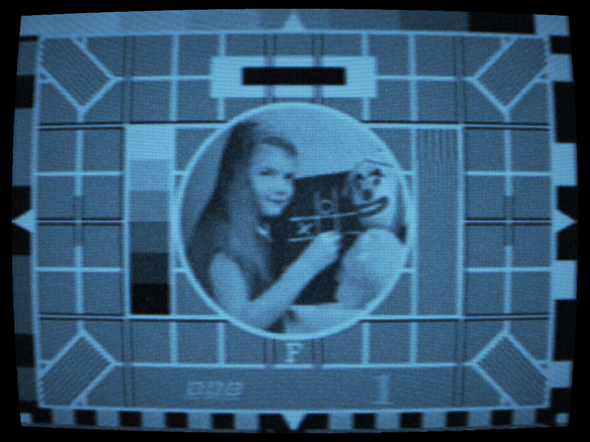
Image Orthicon: dark halo ring, high sensitivity noise
 BURN-IN
CLEAN
BURN-IN
CLEAN
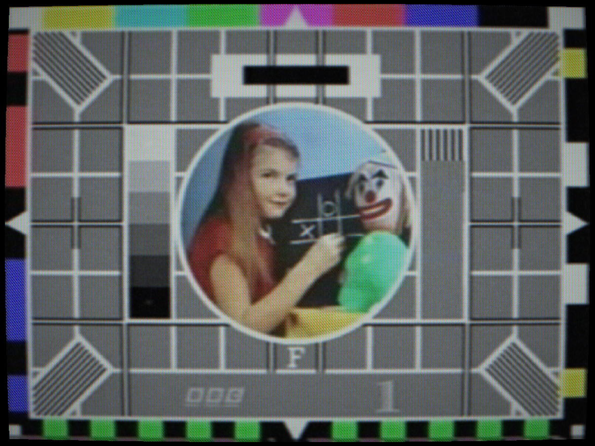
Vidicon: phosphor retention ghost image

 SATICON
CLEAN
SATICON
CLEAN
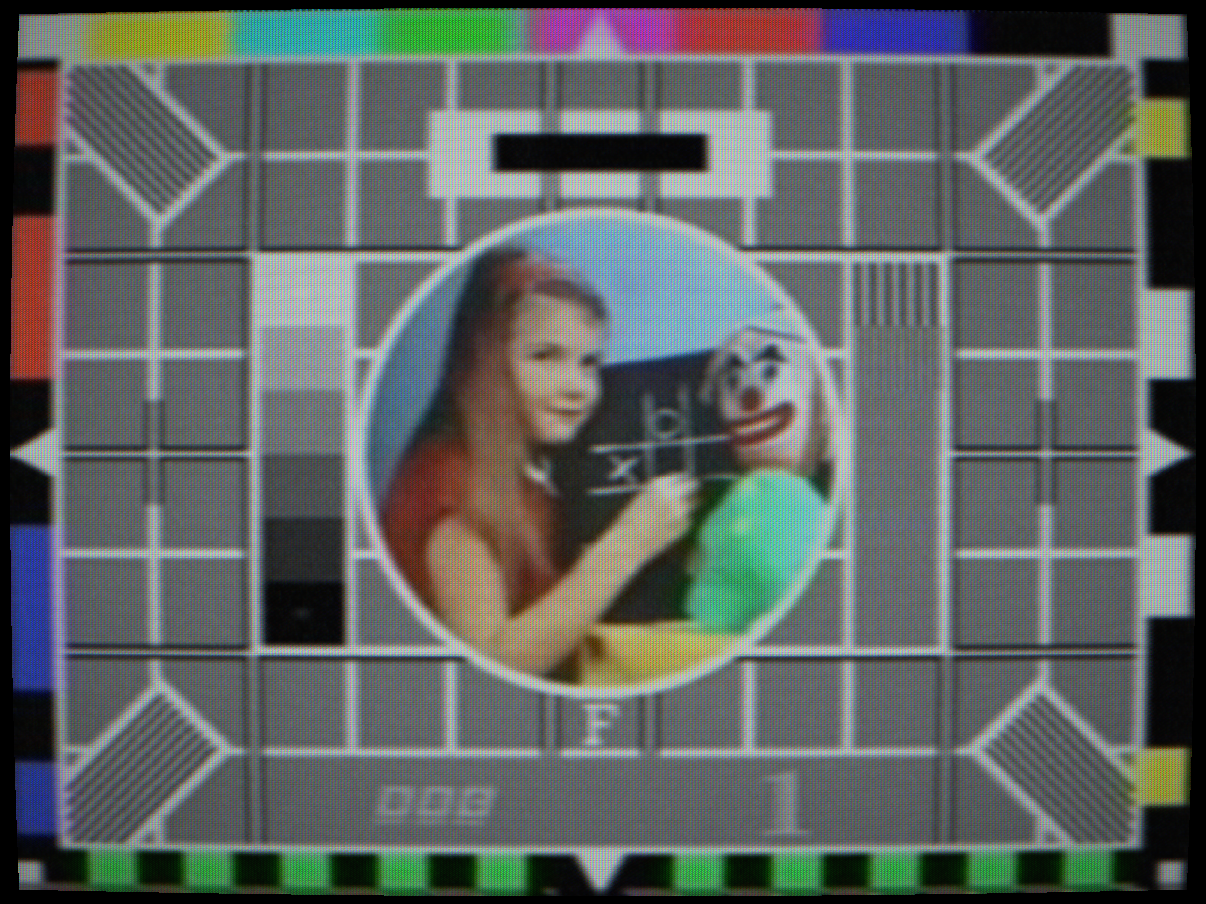
Saticon: SeAsTe, colour fringing, upward vertical smear

 EARLY CCD
CLEAN
EARLY CCD
CLEAN
Early CCD: vertical smear, midtone Poisson noise, registration drift
 TELECINE
CLEAN
TELECINE
CLEAN
Telecine: film grain, 3:2 pulldown jitter, telecine weave
Controls
Selects the broadcast camera tube. Each type is modelled with its own photoconductor gamma, temporal lag impulse response, noise spectral density and optical artefact characteristics derived from primary manufacturer datasheets.
Bypass, no tube simulation; clean digital pass-through.
Vidicon, antimony trisulphide (Sb2S3) photoconductor. Gamma ≈ 0.65, giving lifted shadows and compressed highlights. Slow lag: bright areas comet-tail after movement. Used in consumer and low-cost broadcast cameras from the 1950s through the 1980s.
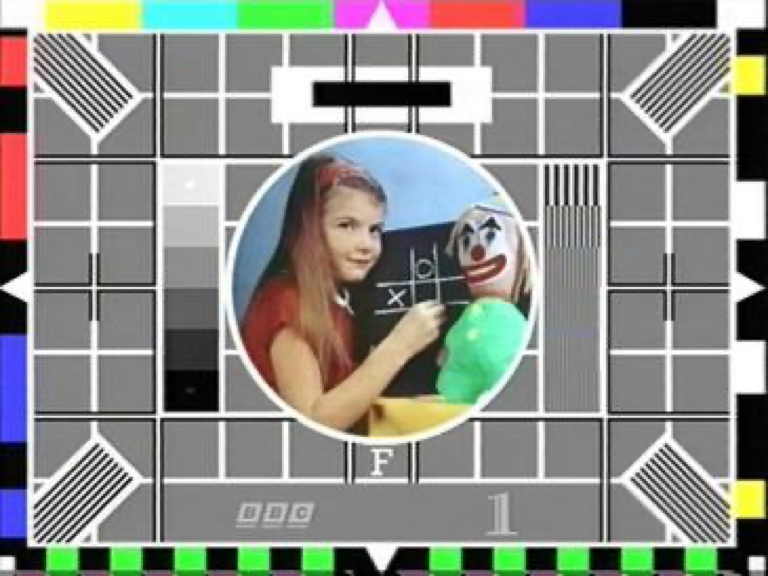
Plumbicon, lead-oxide (PbO) oxide layer. Near-linear gamma, fast lag, low noise. Highlight bloom at the oxide saturation point. The broadcast standard tube for colour cameras 1965–1990. Modelled from Philips Plumbicon datasheet: lag 2 ms at 10 nA/cm².
Image Orthicon, photoemissive mosaic + electron multiplier. Very high sensitivity but the secondary-electron overflow creates a characteristic dark halo ring around bright objects. High lag, pronounced shadow noise amplification by the multiplier. Used in early broadcast cameras from 1946 through the late 1960s.
Saticon, selenium–arsenic–telluride (SeAsTe) photoconductor. Sharper aperture MTF than Plumbicon (Hitachi PF-Z31A: 750 TVL, 58 dB SNR). 3-tube configuration produces colour fringing from registration drift. Characteristic vertical smear upward from highlights, photocarrier diffusion along the selenium layer. Preferred for high-end production cameras, late 1970s–1980s.
Newvicon, cadmium zinc telluride (CdZnTe) photoconductor with a single-tube colour stripe filter. Moderate lag, vertical comet tails on fast-moving objects. Colour bandwidth approximately one-third of luminance bandwidth (~100 TVL colour vs 300 TVL luma), colours bleed horizontally, luma stays sharp. No 3-tube registration drift. Modelled on Panasonic PK-958. Consumer and prosumer use from 1974.
Early CCD, first-generation 3-chip CCD sensors (1980s). Silicon shot noise scales as √signal (Poisson), so noise peaks in the midtones rather than the shadows. Larger prism-block manufacturing tolerances than tube cameras produce more severe colour registration drift. Vertical smear from CCD charge overflow on bright highlights (upward-only, proportional to highlight luminance).
Telecine, film chain/telecine machine. Film grain from silver-halide emulsion (spatially coherent, non-Gaussian). NTSC 3:2 pulldown jitter, cadence-locked to A-frame boundaries. Telecine weave from mechanical film transport instability. Gamma approximately 0.55 (film-to-video transfer characteristic).
SEC (Westinghouse Secondary Electron Conduction), the Apollo lunar-surface monochrome tube. Plano-concave fibre-optic faceplate with characteristic blemishes and a high-gain secondary-electron target. Appears in the tube list only when an Apollo format is selected; paired with the slow-scan format. See the Apollo reference.
SIT (RCA Silicon Intensified Target), the Apollo colour-camera tube behind the field-sequential RGB filter wheel (Apollo 10+ command module and the Lunar Rover GCTA). High sensitivity for low cabin/lunar light; paired with field-sequential colour. See the Apollo reference.
Interactions: Camera Type governs which other camera parameters have physical meaning. IO Halo Strength only matters with Image Orthicon. Highlight Bloom behaves differently for each tube: Plumbicon shows clean spatial bloom; Vidicon shows a broader, softer saturation plateau. Pulldown Jitter only affects NTSC (29.97 fps) sources.
How to test: Switch between types on a colour-bar source with a white area. Watch the corner behaviour, shadow noise and motion lag change. Switch to Image Orthicon and observe the dark ring that appears around the white bar. Switch to Saticon or Early CCD and observe the upward vertical smear from the bright white bar.
Photoconductor charge retention. The photoconductor does not fully discharge between fields; residual charge from the previous frame bleeds into the current one. The simulation uses an IIR (infinite impulse response) filter: out = alpha * prev + (1-alpha) * current, where alpha is the lag value.
The result is a temporal smear on moving objects: bright areas leave a comet tail that decays over several frames. At extreme values, an afterimage of a static object persists long after it is removed from the scene.
Interactions: Temporal Lag interacts with Burn-In Retention, both use IIR accumulators but at very different time constants (lag operates per-field; burn-in accumulates over minutes). Camera Type amplifies lag: the Image Orthicon has inherent lag in the electron multiplier that adds to this control.
How to test: Set lag to 0.3 and wave your hand in front of the camera. A bright smear trails behind the motion. With the Vidicon type, the smear has the characteristic slower decay curve of a real tube.
Oxide layer saturation near the photoconductor knee point. When the photoconductor approaches its maximum charge capacity, excess charge spreads laterally into neighbouring pixel areas, creating a soft radial glow around bright subjects. This is a physical property of the oxide deposition and is especially pronounced in Plumbicon tubes.
The simulation implements this as a weighted Gaussian spread of pixels above the knee point, with the spread radius and weight controlled by this slider. The bloom energy is added back to the luminance channel before encode.
Interactions: Knee Point sets the threshold above which bloom activates. Bloom Strength in the CRT section is a different physical process (electron-optical scatter in the CRT), but the two compound: camera bloom adds to CRT bloom for an overall halo.
How to test: Point the camera at a bright light source or white text on a dark background. Increase this control, a soft white halo expands outward from the bright area. Reduce Knee Point to 0.6 to make the threshold easier to trigger.
Persistent ghost image from prolonged exposure of the photoconductor to a static scene. In real tubes, the photoconductor surface is permanently or semi-permanently altered by the charge pattern of a bright static image, leaving a ghost visible after the source changes. The simulation uses a slow IIR accumulator with a very long time constant (many seconds at maximum) that integrates the image over time and fades slowly.
The effect is most visible after using the test card source for the warmup period, then switching to a dark source, the test card ghost persists as a dim overlay.
Interactions: Warmup period (controlled per capture scenario) and exposure time determine how strong the burn-in ghost becomes. Setting Temporal Lag high alongside Burn-In adds a short-term and a long-term retention component simultaneously.
How to test: Set to 0.7, leave a bright static test card displayed for at least the warmup duration, then switch to a solid black source. The test card ghost image will be dimly visible over the black, fading slowly.
Image Orthicon secondary-electron overflow halo. In the IO tube, the photoemissive mosaic target is scanned by the return beam. When a very bright area is present, secondary electrons overflow beyond the target area and create an anomalous dark ring around the bright object. This is the characteristic “black halo” or “IO halo” seen in all early live broadcast footage from the 1950s and early 1960s.
The simulation models this as a spatially-filtered annular subtraction around pixels above a luminance threshold. The ring width and depth are proportional to this control.
Interactions: Only physically meaningful with the Image Orthicon camera type. At very high values the ring becomes an obvious dark nimbus around all bright objects. Camera Noise amplifies the secondary-electron multiplication noise at the same time.
How to test: Select Image Orthicon camera type, set IO Halo Strength to 0.5. Place a white card (or a bright light) in the camera view. A distinct dark ring approximately 10–20 pixels wide will encircle the bright area, with a brighter outer fringe.
Random thermal noise from the photoconductor and preamplifier. Modelled as additive white Gaussian noise on the luminance channel, applied before composite encode. Different tube types have characteristic noise spectra: the Image Orthicon multiplier adds correlated noise with higher amplitude; the Plumbicon is notably quieter.
Interactions: Camera Noise compounds with Signal Noise Level, both add to the luma channel but the camera noise is added before encode (and therefore shaped by the IF filter), while signal noise is added after decode. In practice both appear as fine grain but the camera noise has a slightly different texture due to the encode/decode filtering.
How to test: Set to 0.25 and view a uniform dark area. Fine random grain becomes visible. Increase to 0.5 to see the noise clearly against a grey field.
Photoconductor gamma correction. Real photoconductors have a non-linear transfer function between incident light and output charge. The Vidicon has gamma ≈ 0.65 (raises midtones, softens shadows). The Plumbicon is near-linear (gamma ≈ 1.0). This control lets you dial in the exact gamma of the simulated tube.
Values below 1.0 brighten midtones and raise the shadow floor. Values above 1.0 push midtones darker and compress highlights more aggressively. Camera chains historically applied an inverse gamma correction at the encoder to compensate for the tube, so this control represents the un-corrected tube characteristic.
Interactions: Use Brightness to compensate for the overall exposure shift that different gamma values introduce. Very low gamma combined with high Highlight Bloom creates the classic Vidicon “glowing midtones” look.
How to test: View a 10-step greyscale ramp. Adjust gamma from 0.5 to 1.5 and watch the midtone placement shift. At 0.65 the ramp should match the characteristic Vidicon curve.
Highlight compression threshold. Above this IRE level, the camera chain applies reduced gain to prevent white clipping. This mimics the knee circuit used in broadcast cameras from the 1970s onward, which allowed filming high-contrast scenes (e.g. a dark studio with bright windows) without clipping the highlights to pure white. The compression slope above the knee is gentler than the linear region below it.
Interactions: The knee point determines the trigger level for Highlight Bloom, a lower knee point causes bloom to activate at lower luminance. Very low knee values (0.55) combined with high Highlight Bloom mimic the characteristic over-exposed look of a poorly set broadcast camera chain.
How to test: View a scene with a mix of dark and bright areas. Lower the knee point from 1.0 to 0.6, highlights compress and become less harsh, while the lower range remains unchanged. Compare with Brightness to understand the difference between level compression and global lift.
Software emulation of the Fujitsu MB88303 TVDC (Television Display Controller) chip as used in the Panasonic PK-958 portapak camera (1983). The MB88303 overlays up to 180 alphanumeric characters in a 9×20 grid onto the composite signal in white, red, green, or blue. Four text size modes are available: 9×20, 9×10, 4×10, and 3×7 character cells, scaling the glyph size while keeping the character count constant. Eight storable text pages allow quick recall of pre-set titles.
The complete 64-character MB88303 ROM is reproduced from the original Fujitsu datasheet patterns, including the MB88303 “Filling” function, automatic inter-grid diagonal smoothing that removes the jagged staircase from diagonal strokes. Text is injected directly into the composite signal before the encoder, so characters pass through the full encode–decode chain: they acquire bandwidth limiting, dot crawl, chroma bleed, and CRT phosphor glow exactly as the real hardware produced them.
Off (no title overlay.
Title) displays the user-entered text from the selected page. Type on the on-screen keyboard; use the Page buttons to switch between the 8 stored pages. The Blink toggle activates the MB88303 global BLINK bit, flashing all characters marked for blink.
Clock, renders the current system time (hh:mm:ss) in MB88303 character style at the selected position. Updates at 1 Hz.
Stopwatch, lap-capable stopwatch displayed as hh:mm:ss:ff (hours–minutes–seconds–frames at the standard’s native frame rate). Tap Start/Stop to run or pause; tap Lap to freeze the displayed time while the internal counter continues running.
Interactions: Title overlay is only active when the source is set to Camera (live, screen capture, or photo library). The overlay is injected before the composite encoder, so all downstream signal artefacts (dot crawl, IF ringing, CRT bloom) apply equally to the title characters and the video.
How to test: Select Newvicon camera type, source to Camera, and enable Title mode. Type a short line of text and set Text Colour to green. Switch to CRT mode with P31 phosphor, the green characters will glow through the phosphor accumulator just as they did on the original hardware.
Silver-halide film grain from the negative and positive print stages of a film chain or telecine. Unlike electronic noise, film grain is spatially coherent, each grain cluster is a micrometre-scale silver crystal whose response is non-Gaussian and correlated across nearby pixels. The simulation generates grain using a spatially-varying noise field that preserves local correlation structure, then modulates it by the local luminance (shadow areas show visible coarser grain; highlights are smoother).
This control is physically meaningful primarily with the Telecine camera type, which represents the film-chain path. It can also be applied to other tube types at lower values to represent the film stock used in studio camera chains before ENG video became standard.
How to test: Select Telecine camera type and set Film Grain to 0.4. Pause on a still frame and zoom in, the grain pattern is static per frame but changes between frames, matching the behaviour of real film grain.
NTSC 3:2 telecine pulldown jitter. Converting 24 fps film to 29.97 fps NTSC requires the intermittent mechanism to hold some frames for 2 fields and others for 3 (the 3:2 cadence). The mechanical intermittent introduces a timing instability at each A-frame boundary, the moment the claw retracts and the film moves on. This produces a subtle horizontal displacement of the entire raster at A-frame transitions only, not every field.
The simulation gates the jitter strictly to A-frame boundaries in the 3:2 cadence, so the artefact appears at the physically correct 6-frame periodicity (~5 times per second at 29.97 fps), not on every frame.
Interactions: Only physically meaningful with NTSC (29.97 fps) sources and the Telecine camera type. PAL and other standards are unaffected. Combine with Film Grain for a complete telecine film chain look.
How to test: Select NTSC standard, Telecine camera type, and set Pulldown Jitter to 0.5. On a scene with fine horizontal detail (e.g., resolution chart), watch for the brief horizontal blur/shift that appears approximately 5 times per second at the A-frame claw retraction.